An example
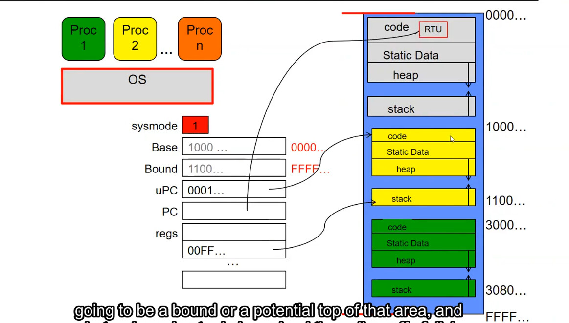
Initially it is in kernel mode; you can notice that its Base and Bound are both disabled (meaning all address space [0000…, FFFF…] is accessible), uPC points to the executable code of the yellow process, indicating that we intend to load into the yellow process.
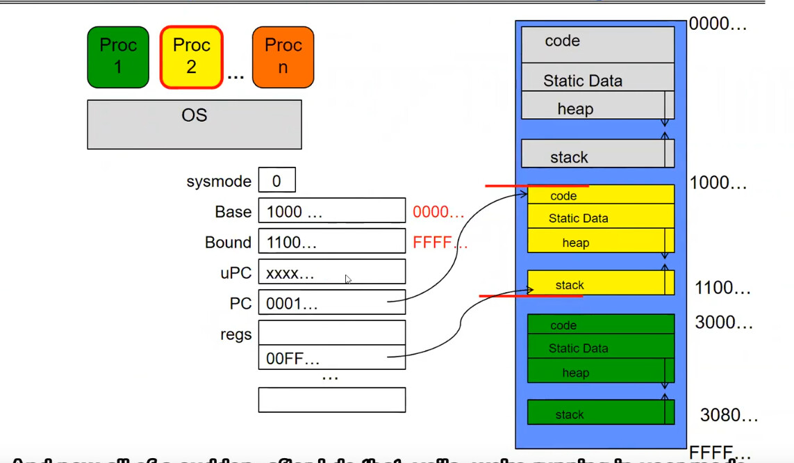
We replace PC with the previous uPC, set sysmode to 0, after which Base and Bound become active and equal to the address region boundaries of the yellow process, meaning we have entered the yellow process and also entered user mode.
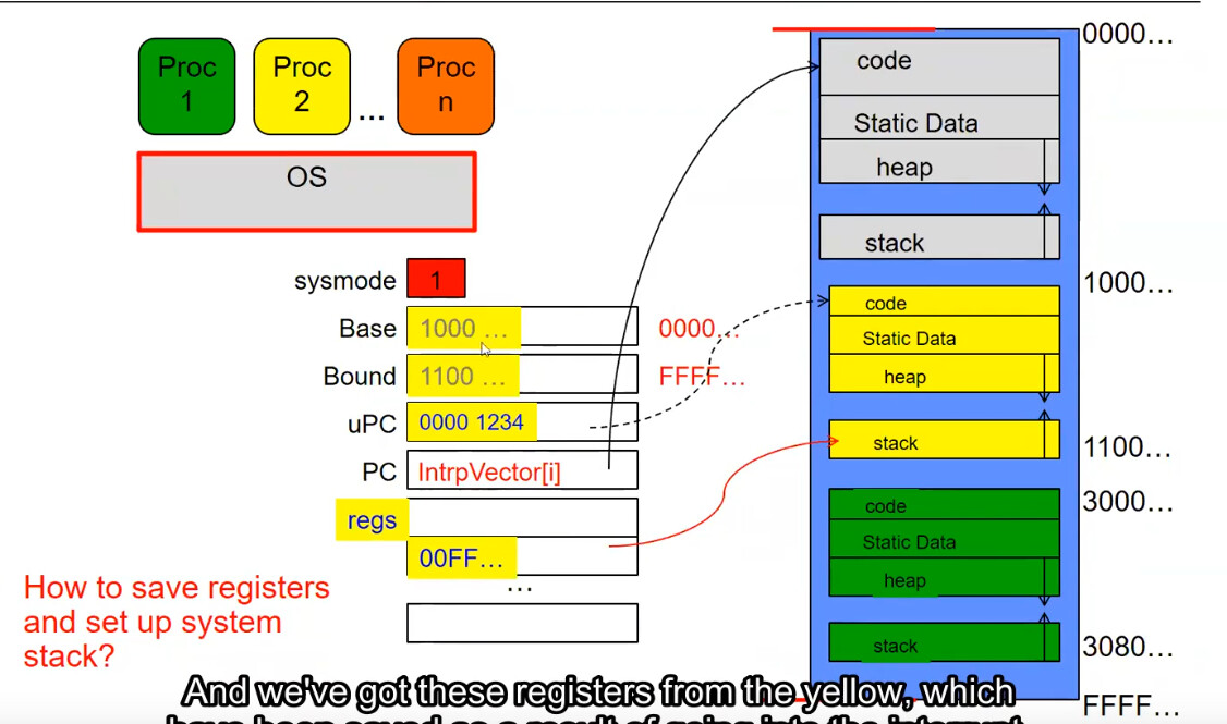
Assume that after some time a timer interrupt occurs; the next instruction to execute will be the timer interrupt handler (located in the kernel code area). After the interrupt, we are once again in kernel mode.
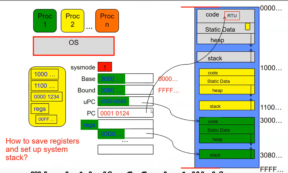
Because a process switch must occur, the timer interrupt handler will save the yellow process’s PCB and place it in the Static Data of the kernel area (gray) as a small yellow block.
At the same time we load the register information needed to switch to the green process.
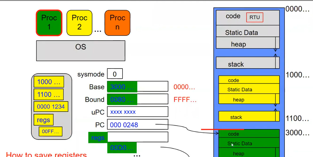
After changing sysmode, the green process runs successfully in user mode.